
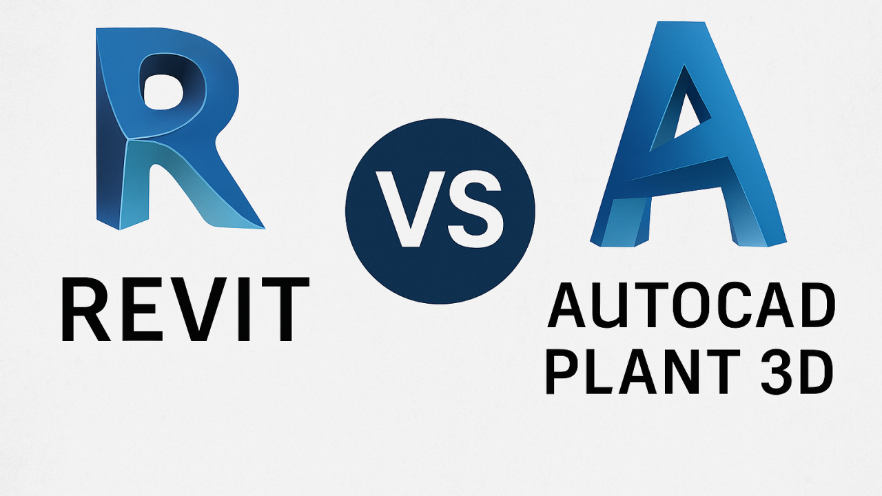
What to Choose for the Project? Revit or Plant 3D?
Question One: What Are We Building?
The most important question that determines everything.
-
If we are building a plant, oil refinery, or chemical production facility – that’s for Plant 3D.
-
If we are building a hospital, business center, or residential complex – that’s for Revit.
Why? It’s simple. Plant 3D specializes in the "insides" of the building. Its world consists of pipes, vessels, pumps, and valves. The building itself is often just a gray box, a shell. Revit, on the other hand, is a genius of the "box": walls, floors, windows, ventilation ducts, and electrical outlets. For it, pipes are mostly comfortable systems: plumbing, sewage, heating.
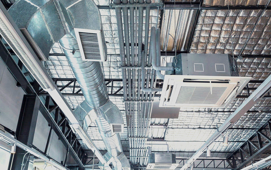
Imagine Designing a Boiler Room
In Revit, I will meticulously model the boiler room itself: load-bearing columns, wall thickness, openings for doors, the ceiling slab, under which there must be a cable duct. Then I will lay out heating pipes with a diameter of 50 mm and install the pump unit.In Plant 3D, I will quickly sketch (or import from Revit) that same gray box and then focus on creating an intelligent model of the process piping: high-pressure pipelines of 300 mm, circulation pumps the size of a car, dirt filters. And importantly, the program will automatically generate isometric drawings, material specifications, and cut the pipes for ordering from the manufacturer.
Question Two: What About The Data?
In Revit, each object is a smart "brick" with data. A wall "knows" what it's made of, its thermal conductivity coefficient, and cost. A pipe "knows" its diameter, working medium, and pressure loss along the section. All this information lives in a single model and translates into schedules, specifications, and floor plans. This is an information model of the building.
In Plant 3D, data is the essence of the project. A pipe is not just a cylinder; it’s an element of the piping network (Piping Line) with a start and end, working medium, pressure, temperature, and insulation. The program automatically calculates lengths, selects fittings (elbows, tees, transitions), and critically important for industrial applications, generates isometric drawings for installers in the field. This is an information model of the technological system.
In Revit: I will draw a DN150 pipe and specify in its properties "Heating Network Supply Pipeline." In the section view, it will be displayed correctly, and its length will appear in the specification.
In Plant 3D: I will create a line "T-1," set parameters: medium = Superheated Water, P=1.6 MPa, T=100°C. I will select steel 20 from the catalog. The program will automatically determine the wall thickness, and when I position the fittings, it will automatically add all flanges, bolts, and gaskets for the valve to the specification. The difference is noticeable.
Question Three: What About Equipment?
Here, too, there is a fundamental difference in approach.
In Revit, equipment (pump, heat exchanger) is typically a loaded family. It has complex geometry and parameters. We can create types, but the flexibility of customization for non-standard products often requires high qualifications.
In Plant 3D, equipment is the base to which pipelines are attached. Here, there is a powerful tool – nozzles. Each hatch, fitting, or nozzle on the equipment is a nozzle with a specific nominal diameter (DN), flange type, and pressure condition. When I connect a pipe to it, the program checks compatibility. You cannot just connect a PN40 pipe to a PN16 fitting – the system will issue a warning. This incredibly prevents silly mistakes in the early stages.
Question Four: Civil or Industrial Project
The boundary is blurred. There is "heavy" civil engineering (data centers, large boiler houses, treatment plants), where Plant 3D is already needed. And there’s "light" industrial work, where Revit can suffice.
Scenario "Industry in Revit": We are designing a small workshop. The technology is simple, and there are few pipelines. We can model everything in Revit using adapted families. The plus – everything is in one model: walls, machines, and pipes. The minus – isometric drawings and specifications for pipes will almost have to be done manually, which is labor-intensive.
Scenario "Civil in Plant 3D": This almost never happens. Imagine trying to design plumbing layouts for apartments in Plant 3D, model a complex suspended ceiling, or place outlets. It’s like hammering nails with a microscope. The tool is not meant for that.
Summary
So what to choose? Let’s break it down simply:
-
Choose Autodesk Revit if your main focus is the building. You think in terms of "room," "floor," "beam," "vent duct." Your pipes are mainly engineering systems for people (heating, water, sewage).
-
Choose Autodesk Plant 3D if your main focus is the technological process. You think in terms of "flow," "line," "equipment," "pump unit." Your pipes are vessels carrying media under pressure, and their correct operation determines the future of production.
In an ideal world, large projects use both packages together. Architects and structural engineers work in Revit, creating buildings and structures. Technologists and mechanics work in Plant 3D, filling these structures with "life" – pipes and equipment. Then the models are consolidated into a single space for collision checking.