
Digital Bridge: Streamlining the Transfer of Working Documentation from Designers to Steel Fabrication Plants
Introduction
In modern steel fabrication, the gap between "paper" and "metal" is often a key source of defects and delays. Design firms develop detailed construction drawings, while manufacturers must transform these files into finished steel structures. However, the transition from the designer's server to CNC machinery is complicated by various factors, such as format incompatibilities, lost documentation, or outdated revisions.
This article explores how to effectively organize the transfer of working documentation packages so that the fabrication plant receives a comprehensive "digital assembly instruction."
1. What is in the Standard Documentation Package?
Before transferring data, both parties must agree on the documentation to be exchanged. A typical package for steel fabrication includes:
- Assembly Drawings: The primary graphical material, usually provided in PDF format (for approval and archiving) and editable CAD formats (e.g., .dwg).
- Detail Drawings: If not included in the assembly drawings.
- Specifications: Tables in Excel or XML formats specifying profiles, steel grades, dimensions, and quantities.
- NC Files: CNC code for machines (thermal cutting lines, drilling centers). The extensions vary based on machine type: .nc, .cnc, .tap, .lst, etc.
- 3D Models: Formats such as IFC, STEP, or the native format of the client's CAD system for visualizing complex joints.
2. Compatibility Issues: Why designer formats sometimes don’t Work for manufacturers
A common mistake is sending raw files from the designer's software (such as Tekla Structures) to the manufacturer without post-processing.
- Software Version Conflicts: The manufacturer may be using an outdated version of AutoCAD or other software that cannot open the file.
- Unreadable NC Files: The post-processor in the designer's CAD system may be configured for one type of machine, while the manufacturer's equipment operates on a different CNC system.
- Missing Links: Exported material schedules may not align with the manufacturer's internal ERP system, leading to manual recalculations.
3. Stages of Transfer: From Approval to Cutting
The transfer process can be divided into three clear phases:
Phase A: Preparation and Conversion
- Export from CAD: The designer exports drawings in a 2D PDF/A format for long-term storage and approval.
- Generation: Ideally, the designer configures settings for the manufacturer's specific equipment. If not, geometry (DXF) is transferred, allowing the manufacturer to generate the NC code.
- Forming Schedules: Specifications are exported in a universal format (Excel or XML) for import into the manufacturer's inventory system.
Phase B: Communication Channels and Transfer Medium
- Cloud Platforms: Use shared folders on cloud drives with access control.
- PDM/PLM Systems: If both companies operate within a unified information space, data can be transferred through the core system with automatic change tracking.
- FTP Servers or Corporate Portals: A traditional method for large manufacturers with regulated IT departments.
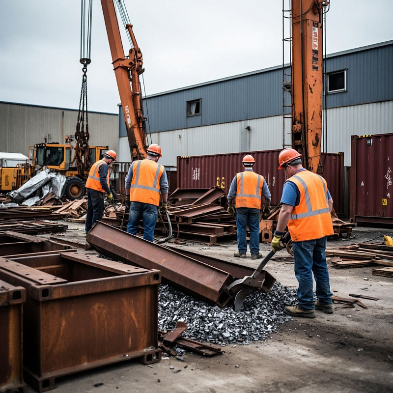
Phase C: Incoming Quality Control at the Plant
- Completeness Check: Ensure all parts are included.
- Test Run of NC Files: Conduct a software simulation of the cutting process.
4. Industry Tips for Perfect Transfer
To minimize human error, professionals recommend:
- Acceptance Checklist: Create a standard form (Excel) for the manufacturer to fill out upon receiving the package. If anything is missing, the package is not accepted for work.
- Stamp in PDF: Each drawing should have a stamp indicating "For Production" or "Approved," signed with a digital signature. This prevents workers from drilling based on outdated versions.
- Material Dictionary: If the manufacturer uses different metal grades (e.g., based on alternative standards), include a compliance schedule for materials.
5. The Future: From File Transfer to System Integration
Leading enterprises are moving from simple file transfers to integrating client CAD/PDM systems with the manufacturer’s MES (Manufacturing Execution Systems). In this scenario, the designer does not just “drop” a folder but grants the manufacturer access to their model. The manufacturer's software retrieves the necessary specifications and geometry, minimizing data entry errors.