
Formwork and Reinforcement Drawings for Monolithic Reinforced Concrete
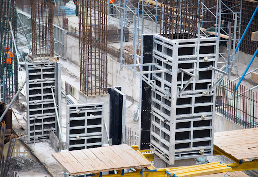
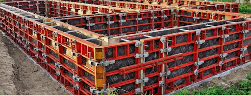
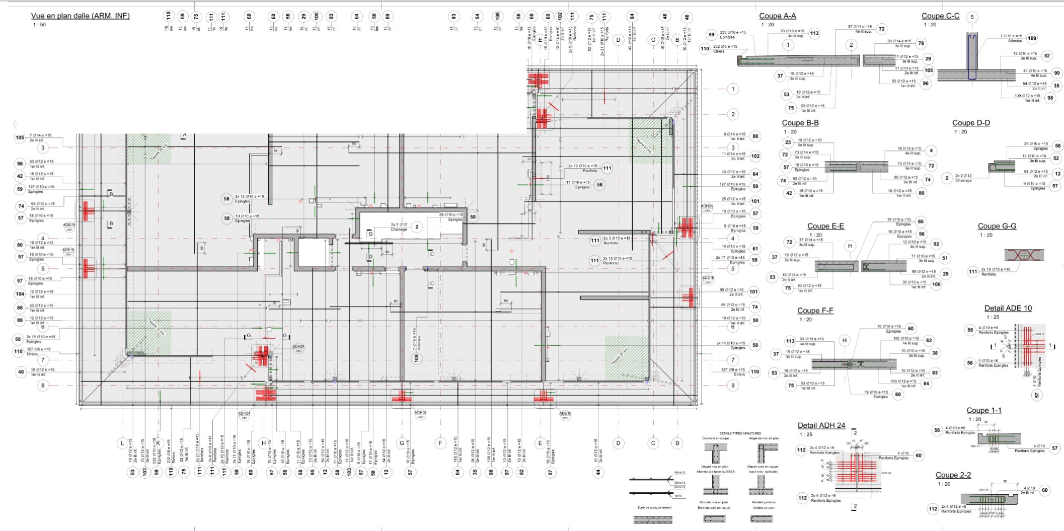
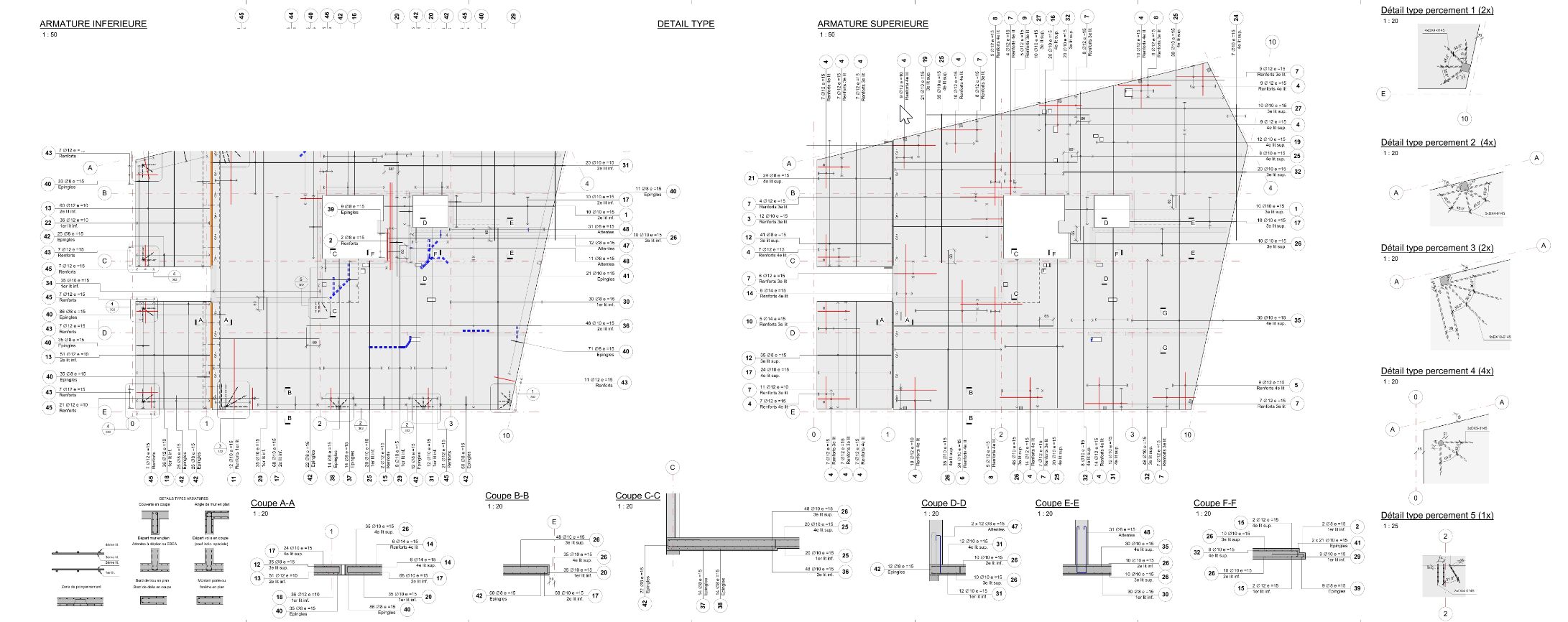
The formwork and reinforcement plans for monolithic reinforced concrete are created based on structural calculations that determine the concrete sections and the amount of rebar required. These drawings include plans, sections, and details that outline the installation of formwork, frameworks, meshes, protective layers, and material specifications, ensuring the precise positioning of elements.
Formwork and reinforcement layouts are developed using BIM technologies (Revit, Tekla) or AutoCAD, encompassing formwork plans, sections with construction references, and placement schemes for meshes/frameworks indicating spacing, diameters, concrete protective cover (25-30 mm), and material specifications.
The Process Includes:-
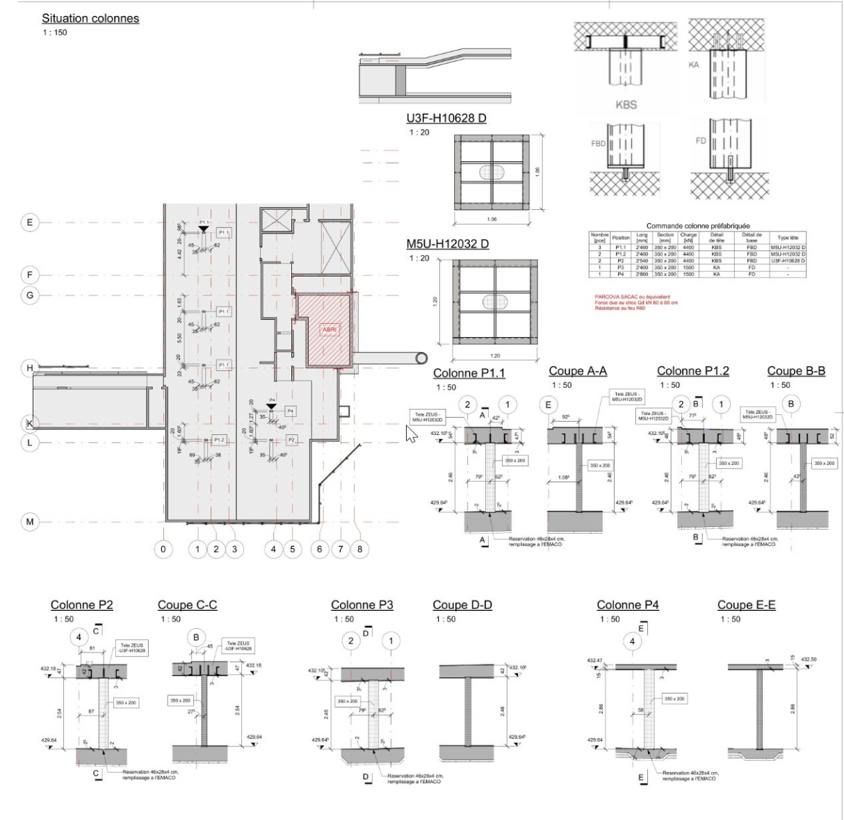
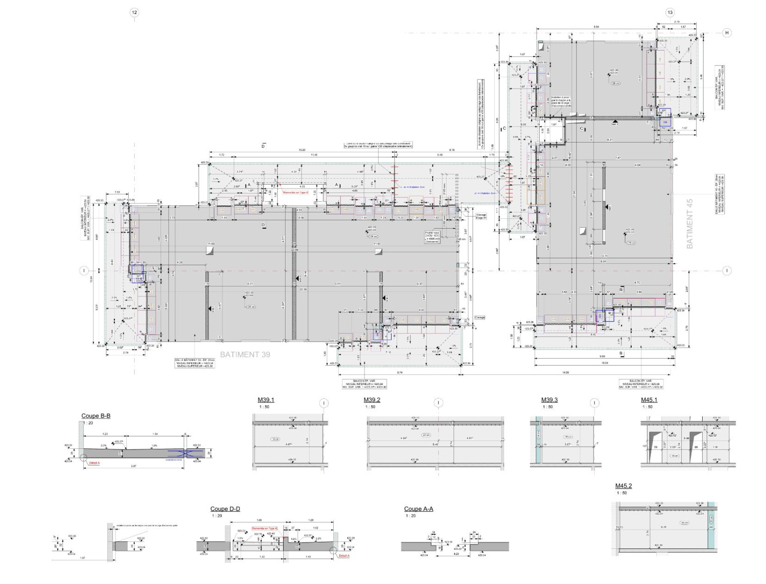
Formwork Drawings: Define geometric dimensions, references to axes, elevation marks, locations of openings, and embedded parts.
- Rebar Detailing: Illustrate the top and bottom meshes (for slabs) with the spacing of spacers (500-600 mm), vertical/horizontal reinforcement (for walls) with indications of extensions.
- Specifications: Tables showing rebar usage (A400/A500) including diameters, lengths, quantities, and weights, along with concrete volumes.
-
Detailing: Junction details for walls, columns, and slabs.
To enhance efficiency, BIM standards are utilized, enabling the automatic generation of sections and specifications, thereby minimizing errors in reinforcement.
Key Stages in the Layouts Development:
Formwork Drawings:
-
Positioning: Accurate positioning of walls, columns, and slabs on the plan.
-
Dimensions: Specification of geometric dimensions, elevation marks, and openings.
-
Nodes: Details of formwork panel joints, slab formwork setups, and corner elements.
-
Specifications: A list of formwork elements.
-
Reinforcement Drawings:
-
Laying Schemes: Show longitudinal and transverse reinforcement, mesh spacing, and bar placement.
-
Sections: Display the concrete protective cover (typically 30–50 mm).
-
Specifications: A table indicating diameter, length, quantity, and mass of reinforcement.
-
Anchoring Nodes: Details of rebar extensions for connection with subsequent pours.
Technical Features:
-
For foundations, mesh (1-2 layers) is used; for walls, vertical and horizontal bars; for slabs, both top and bottom reinforcement are employed.
-
Drawings often include notes regarding the reusability of formwork and concrete grades.
-
Preferably, welded frames and meshes manufactured off-site are used.
When preparing the drawings, we always request templates from the client to ensure that they are comfortable and familiar with the drawings for future use.
ENECA Group specializes in creating 3D models of reinforced concrete structures using Autodesk Revit and Tekla Structures.
Our services:
- Development of plans: formwork plans, reinforcement plans
- Development of drawings: General arrangement drawings, Workshop drawings for prefab elements
- Static and dynamic calculations of reinforced conсrete structures as well as geotechnical calculations
- BIM modeling of precast and cast-in-situ (cast-in-place (CIP)) and monolithic structures including prestressed concrete up to LOD400